Abstract
The article outlines a systematic approach to identify specific problematic stages in WG production lines. This is achieved by measuring the particle size distribution after each production step and subsequently analyzing the obtained PSD data matrix. The author is available to help in implementing this approach, contact the author.
The production of WG formulations requires precise manufacturing processes. Technical problems can occur at various stages, leading to degradation of product quality. The main challenge is to identify the specific production step where a problem exists. Sometimes there could even be multiple issues at different stages.
The following methodology involves conducting comprehensive particle size distribution (PSD) analysis at each stage of the production line using advanced particle size measurement techniques. This approach identifies deviations from the desired PSD profile at each stage and enables the creation of a PSD matrix to analyze multiple data obtained stepwise. This provides insights into potential technical issues. By identifying these issues early, manufacturers can take targeted interventions to optimize the production line and improve product quality.
Measurement PSD
To obtain reliable particle size distribution data, it is necessary to use the most advanced PSD measurement techniques. It could be one of the following methods:
- Laser Diffraction: This method passes a laser beam through the sample and uses the scattering pattern to determine particle size distribution. Instruments like Malvern Mastersizer and Beckman Coulter LS are commonly used.
- Dynamic Light Scattering (DLS): DLS measures light intensity fluctuations from scattered particles to determine their size. Instruments such as Zetasizer and Malvern NanoSizer are frequently used for DLS analysis.
WG formulation process
The WG formulation process consists of the following stages, which can be realized by different equipment and process methods:
- Mixing tech. A.I. with other excipients for the following grinding of the formulation premix
- Grinding, e.g., air jet milling
- Wetting
- Granulation, e.g., extrusion granulation (through basket extruder), spray and spray drying granulation, fluidized bed granulation, Flexomix agglomeration (wet granulation), etc.
- Drying, e.g., fluidized bed drying, tray drying, belt drying, spray drying
- Sieving, packaging, and storage of the final product.
What is successful and what is problematic particle size distribution
The overall goal of the WG process is to produce a granulated product with each granule consisting of particles of a specific size and a narrow, monomodal PSD. The particle size distribution requirement must be maintained throughout the entire production process, from the grinding stage to the final output. Maintaining the desired PSD profile throughout the production process indicates a successful process. Any changes in the profile at a particular stage suggest issues at that stage or at the preceding stages. Such changes as an increase in the size of larger particle fractions can negatively impact product quality.
Particular attention should be paid to the particle fractions represented by 90% (D90) and 99% (D99) of the distribution, while these values indicate the maximum particle size for 90% and 99% of all particles, respectively. An increase in the size of these fractions suggests the presence of larger particles remaining after grinding, or the formation of agglomerates during one of the stages. These larger particles or agglomerates can lead to clogging of filters and nozzles during field application, as well as to instability of the formulation during storage.
If the particle size distribution profile changes from a narrow, monomodal distribution to a broader, bi- or multimodal distribution, it indicates potential deterioration of the formulation in subsequent process steps.
STEP-BY-STEP MONITORING OF PSD
Now, let's see what we can learn from the particle size distribution (PSD) results obtained for each production step.
Step 1. Mixing of the formulation premix before grinding.
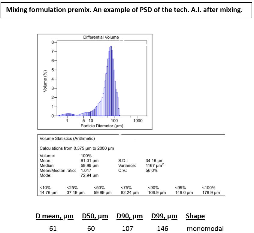
The chart shows an example of the PSD for active ingredient (A.I.) particles after the A.I. has been mixed with other excipients of WG formulation. Dispersants added to the A.I. allow the mixture to be dispersed in water. It is important to note that the presented profile is just one of many possibilities and is provided for illustrative purposes only. The chart above shows the formulation with one AI. The large particles are about 100-150 µm.
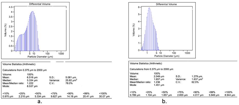
Step 2. Grinding
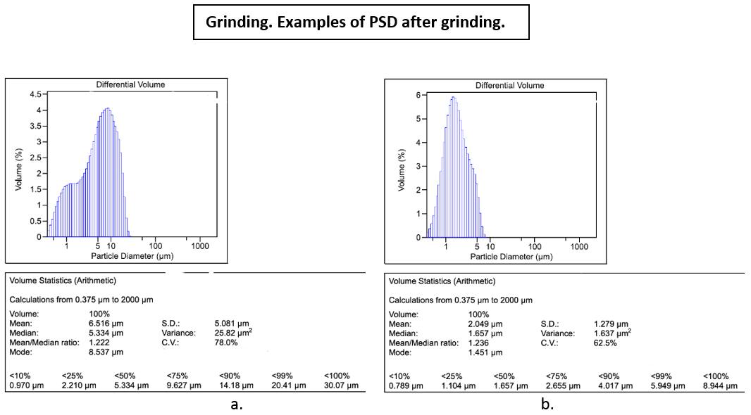
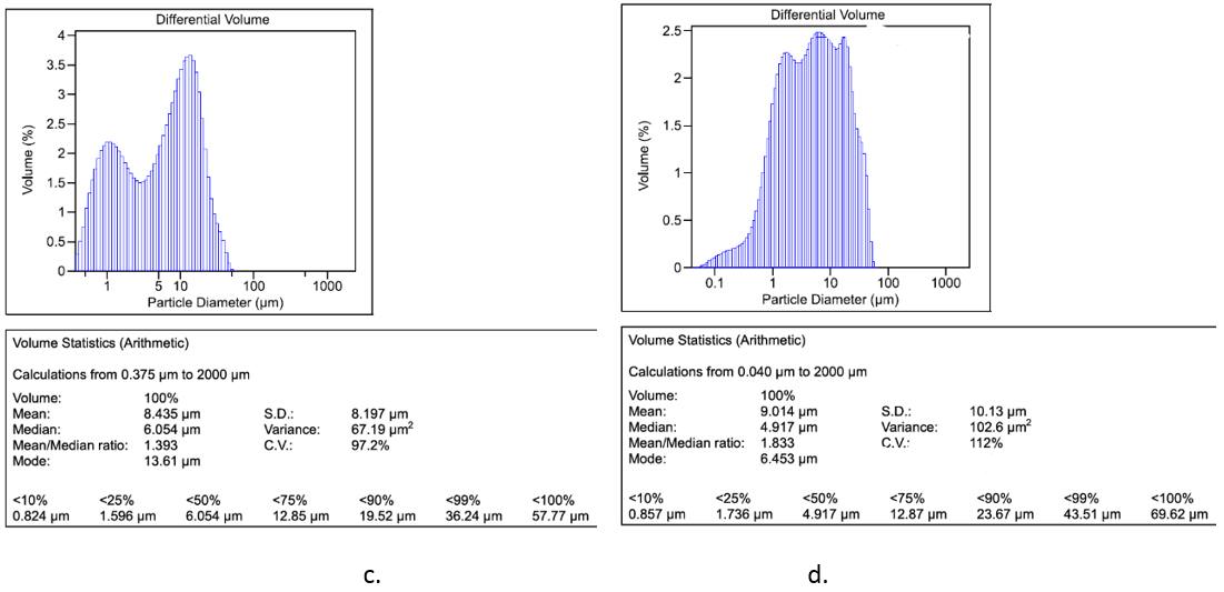
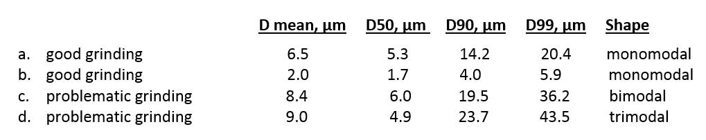
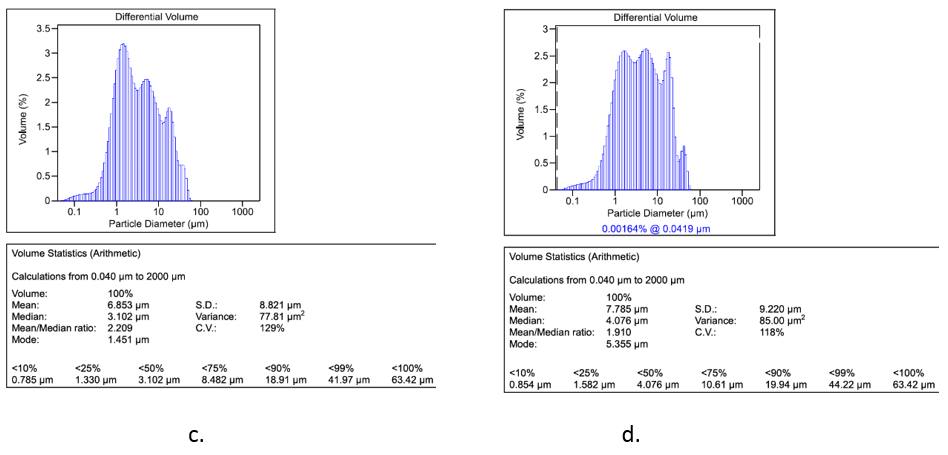
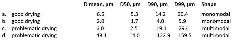
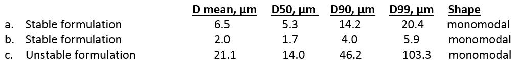
Charts a and b show examples of close to monomodal, narrow PSD after grinding. The large particles D90 and D99 are with sizes of about 14-20 and 4-6 µm. This is a good target PSD, and it should be maintained without significant changes throughout the entire process.
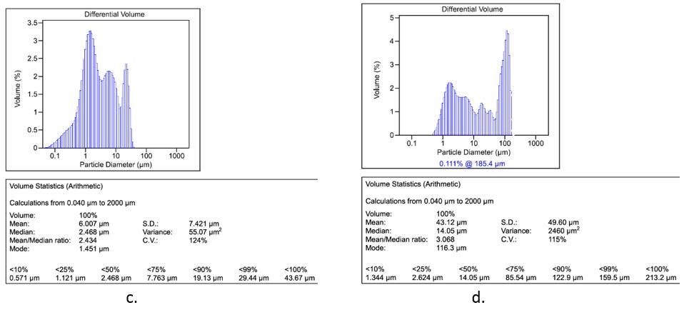
Charts c and d show problematic grinding (for air jet milling it could be a mill without classifier). In these cases, the grinding process left a wide, multimodal PSD. This is characterized by rest of the large particles in granules, with D99 values of 36-44 µm. The next process steps may only further deteriorate this PSD, leaving the potential for further quality and stability issues. It is important to note that the presented profiles are for illustration only, there may be other possible PSD profiles.
Step 3. Wetting
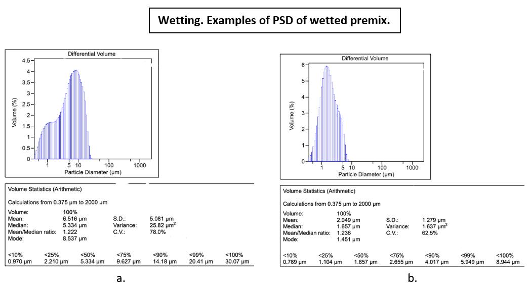
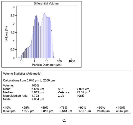
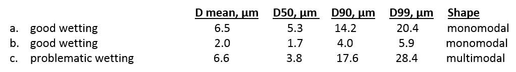
Charts a and b show the examples of unchanged PSD obtained in the previous grinding stage. Chart c shows problematic wetting, which resulted in a change from a monomodal PSD profile to a multimodal profile. This could potentially lead to problematic granulation, which could further deteriorate the PSD of the final product. It is possible that this problem will not cause any problems with the PSD or stability of the final product, but it will negatively affect the appearance of the granules and the overall yield of qualified granules, leaving a lot of fines to be reworked.
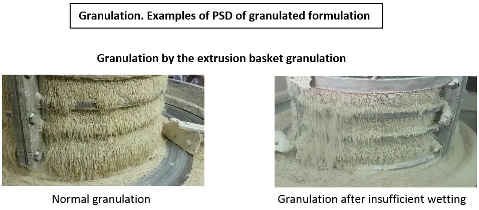
The photo below shows an example of undesirable granulation that can occur when using the extrusion basket granulation method after improper wetting. This is just one example of the various undesirable outcomes that can occur due to insufficient wetting.
Step 4. Granulation.
Charts a and b present unchanged particle size distributions obtained during the preceding stages.
Conversely, charts c and d display examples of problematic granulation steps that result in wider, multimodal PSDs. This outcome will undoubtedly lead to an inferior PSD after drying, subsequently exacerbating product instability during storage. Over time, this is likely to further degrade the PSD, leading to poor dispersion in water when applied in the field.
To reiterate, the particle size distributions depicted in the above charts serve as illustrative examples of the potential changes in PSD that may arise following inadequate granulation. They are presented solely for the purpose of demonstration.
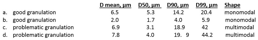
Step 5. Drying
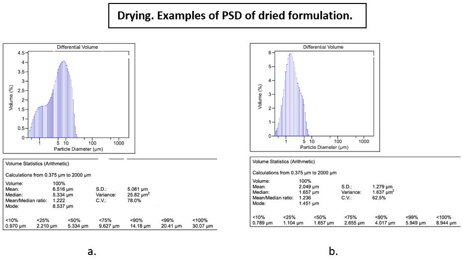
Charts a and b show unchanged particle size distributions obtained during the preceding stages.
Conversely, charts c and d show examples of further degradation of PSDs. This is the final product output from the line prior to sieving and packaging. Unfortunately, such a product should be rejected.
Damage to particle size distribution after drying can also be caused by a problematic formulation. To understand this possibility or to modify drying conditions, it is necessary to compare data obtained after drying at different temperatures and durations during laboratorial development. This comparison enables a better understanding of the impact of formulation and aids in optimizing the drying process.
Step 6. Sieving, packaging, and storage of the final product.
Next, consider examples of the PSD of the final product after storage. It is important to re-test samples on stored lots in the warehouse after one or two months to make sure they are suitable for shipment to consumers.
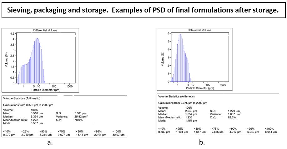
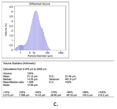
Charts a and b show the examples of PSD remaining unchanged after storage. Chart c provides an illustrative example of the PSD showcasing the increase in particle size following storage. Certainly, there are various other possibilities of damaged PSD profiles, including multimodal distributions, skewed distributions, or irregular patterns. This phenomenon can be attributed to:
- Adverse storage conditions, such as elevated temperature, humidity, non-hermetic packaging, or caking resulting from stacking large bags on top of each other.
- Another factor contributing to the deterioration of PSD after storage may be the earlier degradation of PSD during one of the preceding steps in the production process. Therefore, conducting a step-by-step analysis becomes crucial as it allows us to pinpoint the exact stage where the problem originates.
- Furthermore, another possible cause of PSD deterioration could be an unfavorable composition of the formulation. To investigate this, it is essential to compare the storage results with the storage stability outcomes obtained at different temperatures during the formulation's development in the laboratory. This comparative analysis provides valuable insights into the potential impact of formulation composition on PSD changes during storage.
KNOW-HOW
ANALYZING THE OVERALL STEP-BY-STEP PSD DATA
To effectively analyze the overall data derived from the step-by-step PSD analysis, we can construct a PSD data matrix. This matrix will use a “+” symbol to indicate a desirable PSD profile or the appropriate appearance of granules, and a “-“ symbol to denote any technical issues encountered at specific stages. The table below presents the PSD data matrix for all possible scenarios.
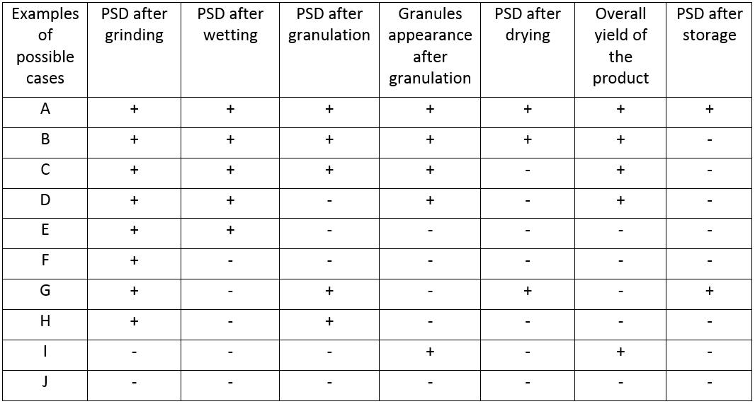
Row A represents the optimal scenario where no issues arise throughout the entire process. Row B illustrates a situation where the PSD profile is damaged after storage, prompting us to consider reasons 1) or 2) as potential causes. Rows C-J encompass the various problem variations that can occur at different steps of the WG formulation process.
When issues regarding the quality or stability of a WG product arise, it is crucial to perform a step-by-step PSD analysis. By systematically collecting samples at regular intervals from various process steps and different batches and organizing the PSD analysis results in a similar matrix or table, it is possible to identify the specific process step responsible for issues in the final product.
In some cases, it may be necessary to compare the results with storage stability data obtained during formulation development to eliminate process stages as potential causes of degradation or to modify process conditions at these stages.
Conducting such a comprehensive analysis is a valuable tool for identifying the root causes of problems within the complex, multi-step process of a WG manufacturing line.